Sensors and Stepper Motors
This page provides guidance on sensor integration.
Tracker Sensor HW-006
The digital tracker sensor HW-006 is a device that emits infrared lights and detects reflected light. In this way it is possible to detect the proximity of a (sufficiently reflecting) object, or to detect wether the surface below the sensor is dark (non-reflecting) or light (reflecting).
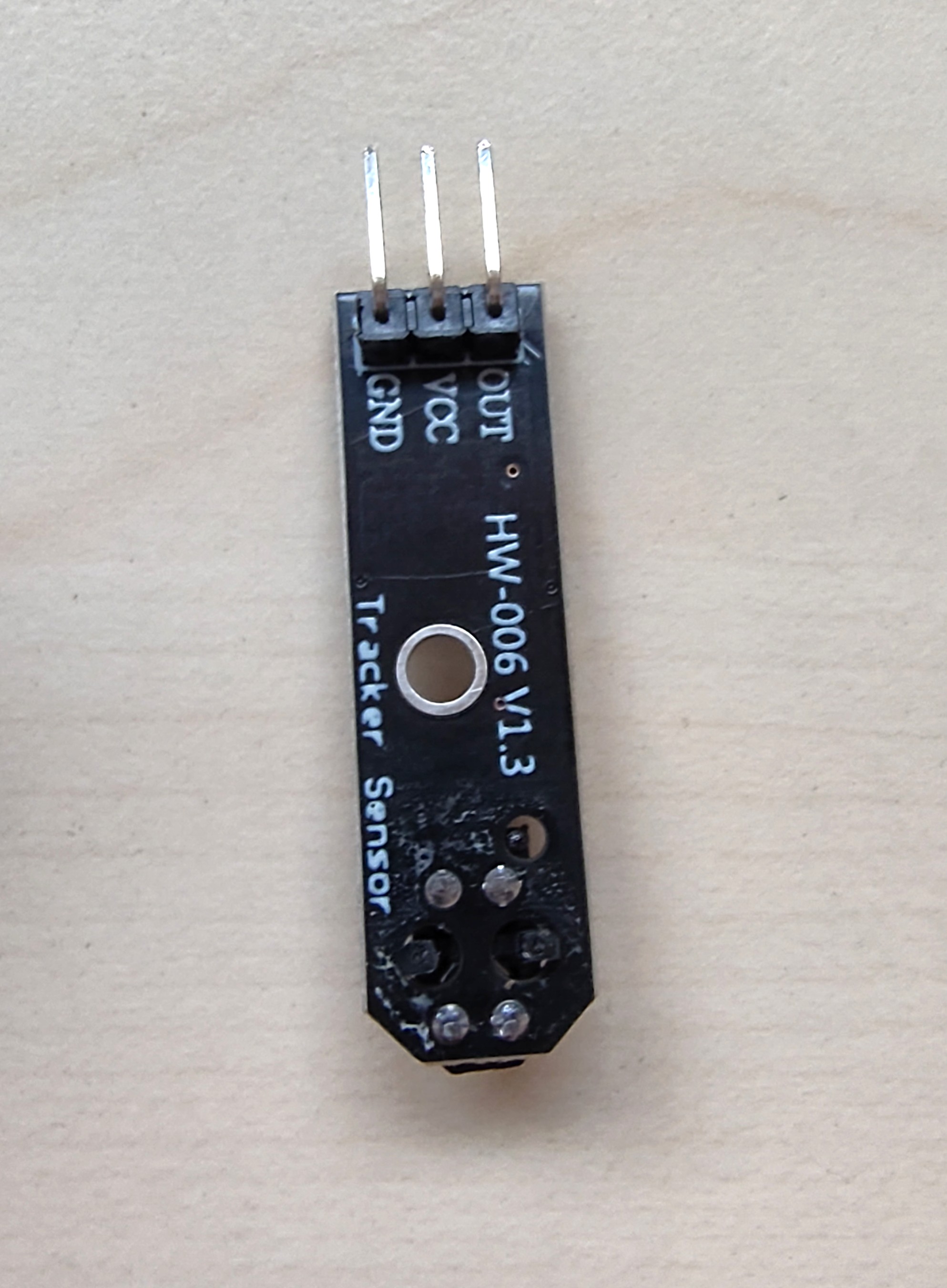
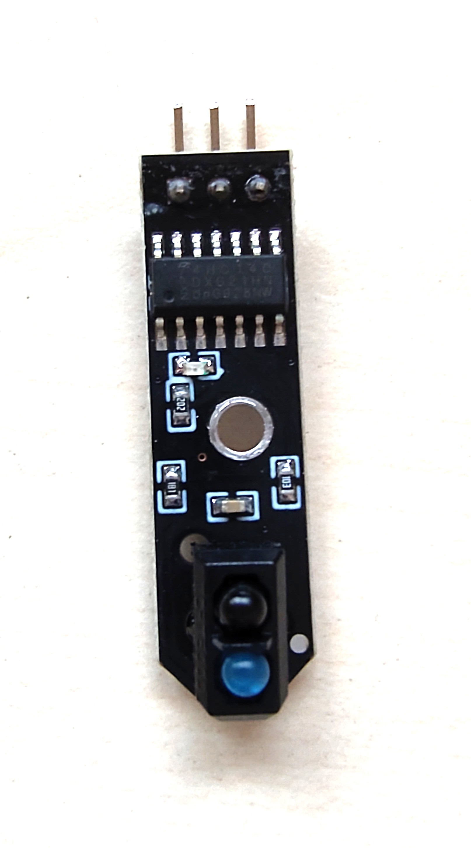
Experience shows that the sensor may be hindered by environmental light or spurious reflections, leading to the sensor only working accurately when positioned very close to the surface. In that case, it may help to add a cover to the emitter-detector pair as shown in the image below. You will be provided with such covers that fit tightly on the device.
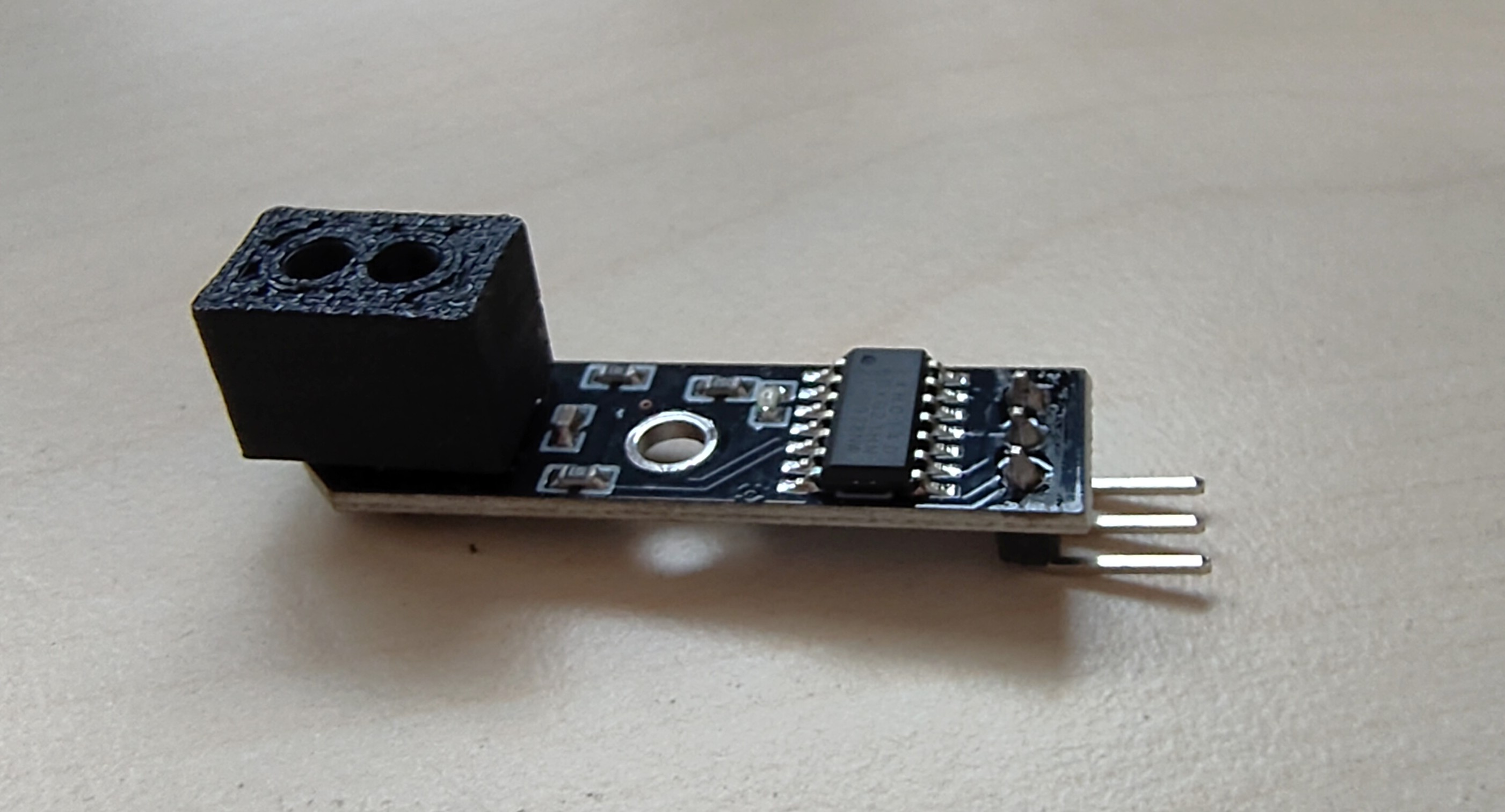
⚠️ Warning Some surfaces that appear black to the eye may still be reflecting infrared light. We have experienced cases where the sensor was unable to detect a printed black line due to the ink not (sufficiently) absorbing infra-red light
The sensor is connected to power (3.3V and GND). It delivers a single digital output that is LOW when reflected light is detected and HIGH otherwise. It should be connected to a GPIO pin of the PYNQ board.
The three connecting pins can be identified on the photo above.
VL53L0X Distance Sensor
The VL53L0X sensor, from ST Microelectronics, is a time-of-flight laser-ranging module, enabling distance measurement. It emits laser infra-red light, and detects light reflected back to the sensor to determine the distance to the reflecting object using the time-of-flight of the light.

Integration with PYNQ Board
- The sensor interfaces with the PYNQ board via the connectivity board, which routes I2C communication through specific pins designated for this purpose. This integration facilitates using the I2C protocol via the provided Arduino headers (AR SCL and AR SDA pins).
- The communication with the VL53L0X is more complex than, for example, the line follow sensor as it involves setup and configuration. These communications are provided in library software,
vl53l0x.hand implemented invl53l0x.c. - You may base you initial code for using the distance sensor on the provided example applications
tof-sensor, andtof-sensor-ledbar. - More information can be found in the documentation of the Application Programmer's Interface (API)
- the sensor’s data sheet.
ℹ️ Information Study the example applications
tof-sensorandtof-sensor-ledbar. It uses functions defined invl53l0x.hand implemented invl53l0x.c. Have a look at these too.⚠️ Warning If you are using the ToF sensor together with the LED bar, measures may need to be taken to mitigate interference. See the remark at the LED Bar description.
Practical Implementation Tips
- The device can be power with 3.3V or 5V. We will use 3.3V.
- Ensure the wiring is correct:
Vinto3V3,GNDtoGND,SCLto!SCL, andSDAto!SDA. - Reuse the provided functions in
examples/lib/DistSensorAPI/vl53l0x_pynq_api.h. - Check out the full API in the folder
examples/lib/DistSensorAPI/vl53l0x_api.h
Troubleshooting
- If the device shows a failure to initialize or to communicate, try resetting the device by disconnecting and reconnecting.
- If the above does not work, check if the connectors or cables are damaged.
The ArduCam SPI Camera

The camera is the ArduCam Mega 3M with an SPI interface. It incorporates a lens and CMOS sensor to capture color images.
Integration with PYNQ Board
The SPI master-slave interface (although the 'master-slave' terminology is considered deprecated, it is used historic reasons) works with four wires, a clock signal SCK, two data communication wires, labelled MISO (Master Input Slave Output) and MOSI (Master Output Slave Input), and finally a CS (chip select) signal to activate the peripheral device communication.
The PYNQ board includes an SPI module in its programmable logic component, which can be connected to IO pins of the PYNQ or its connectivity board. The provided example software (examples/camera) is set up to use the connections (AR9-AR12) (see the IO page).
ℹ️ Info The high-speed communication lines (
SCK,MISO,MOSI) may not work properly in combination with the protection resistors that sit between the Arduino header on the connectivity board and the PYNQ. Use a board where the protection resistors are removed or replaced by 0Ω resistors.
Practical Implementation Tips
The use of the camera is illustrated with the provided camera example application. The file capture.c illustrates how to set up the camera and trigger it to take a picture. In the given mode, the camera communicates the picture using JPEG encoding.
Check also the Arducam.c and Arducam.h files that show the functions in the camera API in case you want to use additional advanced features of the camera.
LED bar

The robots contain a LED bar that may be convenient for providing visual feedback to the user, for example about the internal state of the software, or simply for nice visual effect.
The LED bar is based on the RGB LED WS8212. It uses an 800kHz one-wire protocol to serially communicate 24bit RGB color information to each of the LEDs.
⚠️ Warning The LEDs can be very bright to look at directly at close distance when used at full intensity.
Integration with PYNQ Board
Since the 800kHz signal for the one-wire protocol cannot be generated from the ARM processor on the PYNQ board, a dedicated hardware module is present in the programmable logic of the PYNQ in the 5AID0 image. The color values to be displayed can be communicated to the hardware module from the ARM processor using shared memory.
Check out the ledbar and tof-ledbar example applications to see how the LED bar can be used.
The interface is implemented in the file examples/lib/ledbar/ledbar.c and corresponding header file. It allows the color of each of the eight LEDs to be controlled. The color is encoded with a 32 bit integer in which the 8 least significant bits, representing a number between 0-255, indicate the intensity of the blue color, then 8 bits for the red color and 8 bits for the green color. Note that the order is not RGB, but GRB (from most significant to least). The 8 most significant bits of the 32 bit number are not used.
The 32 bit value 0x00A5FF00, for example, represents an orange color with (R, G, B)=(255, 165, 0).
It is further possible to halt or resume the updating of the LED lights with the programmed colors. In this way it is possible to make all 8 LEDs change color simultaneously.
The library functions communicate the LED colors through shared memory to a hardware timer implemented in the programmable logic of the PYNQ board that controls the physical communication to the LED bar.
Practical Implementation Tips
The led bar data wire carries a 800kHz signal that communicates the LEDs colors to the LED bar. We have experienced potential interference issues when this wire is very close to other data communication wires, specifically the I2C communication with the distance sensor may prove to be susceptible. When the suggested pins are used, this issue should be sufficiently mitigated.
In the SD-card Image for 5AID0 (version 5AID0-2025-v0.2), for IIC1 additional robustness features have been enabled. Hence, the use of IIC1 (instead of IIC0) for the ToF sensor is recommended when used together with the LED bar.
Stepper Motors
The robots' movement is controlled by high-precision stepper motors, selected for their accuracy and reliability in navigation, especially in challenging environments. A stepper motors does not rotate like a normal motor, but instead takes (many) small fixed-size steps and when not moving it holds the current position. In the current setup to make one full wheel rotation, you need to request 1600 steps:
// Initialize the stepper driver.
stepper_init();
// Apply power to the stepper motors.
stepper_enable();
// Move one full rotation.
stepper_steps(1600,1600);
The above code initializes the stepper driver, powers on the stepper motors and makes the robot move with both wheels forward by one full wheel rotation. To move the robot backwards you specify a negative number. The maximum number of steps per command is 32767, which amounts to ~20.5 rotations.
You can call stepper_steps while the robot is still moving, it will then
continue with the next command directly after finishing the current. You can use the function stepper_steps_next_done
to determine when there is space in the command buffer to submit the next movement command.
It is also possible to change the speed of the wheel rotation, before requesting it to step you can set a speed per wheel:
The speed here is defined in time between each step, so the bigger the number, the slower the steps. The minimum is 3024 (~30uS per step, ~50ms per rotation) and the maximum is 65535 (655uS per step, ~1sec per rotation).
⚠️ Warning Be careful. When moving too quickly, the robot could easily topple over on start or stop. To prevent toppling, the motors are released immediately after the scheduled motion ends. The downside is that the robot may slightly move after the motors are released. It may be advantageous to accelerate into a movement and decelerate to a halt at the end. See the provided
examples/stepper-motor-accelexample application.
Below is some sample code that listens on MQTT for a json formatted command and translates this into movement. It reports the current state back.
#include <arm_shared_memory_system.h>
#include <json-c/json.h>
#include <json-c/json_object.h>
#include <libpynq.h>
#include <platform.h>
#include <stdint.h>
#include <stepper.h>

void uart_read_array(const int uart, uint8_t *buf, uint8_t l) {
  for (uint8_t x = 0; x < l; x++) {
    buf[x] = uart_recv(uart);
  }
}

int main(void) {
  pynq_init();
  switchbox_set_pin(IO_AR0, SWB_UART0_RX);
  switchbox_set_pin(IO_AR1, SWB_UART0_TX);
  gpio_set_direction(IO_AR2, GPIO_DIR_INPUT);
  gpio_set_direction(IO_AR3, GPIO_DIR_INPUT);
  printf("AR2: %d\n", gpio_get_level(IO_AR2));
  printf("AR3: %d\n", gpio_get_level(IO_AR3));

  uart_init(UART0);

  uart_reset_fifos(UART0);

  stepper_init();

  stepper_enable();

  stepper_set_speed(1000, 1000);

  stepper_steps(100, 100);


  while (1) {
    if (uart_has_data(UART0)) {
      uint32_t size = 0;
      uart_read_array(UART0, &size, 4);
      char array[size];
      uart_read_array(UART0, &array, size);
      printf("data: %.*s\n", size, array);

      json_tokener *tok = json_tokener_new();

      json_object *root = json_tokener_parse_ex(tok, array, size);
      if (root) {
        int16_t l = 0, r = 0;
        json_object *lo = json_object_object_get(root, "left");
        if (lo) {
          l = json_object_get_int(lo);
        }
        json_object *ro = json_object_object_get(root, "right");
        if (ro) {
          r = json_object_get_int(ro);
        }
        json_object *so = json_object_object_get(root, "lspeed");
        json_object *sor = json_object_object_get(root, "rspeed");
        if (so && sor) {
          uint16_t s = json_object_get_int(so);
          uint16_t sr= json_object_get_int(sor);
          stepper_set_speed(s, sr);
        }
        printf("%d %d\n", l, r);
        stepper_steps(l, r);
        json_object_put(root);
      }
      json_tokener_free(tok);
    }

    usleep(1 * 1000);
  }

  while (!stepper_steps_done())
    ;

  stepper_destroy();

  pynq_destroy();
  return EXIT_SUCCESS;
}
Example message:
For more information see libpynq documentation and pynq user documentation.