Overview PYNQ Input/Output (I/O)
This page describes general PYNQ I/O. For both courses, a specific description is available using their respective libraries. See 5EWC0 (RYB), 5EWC0 (EC), 5EIDO, 5AIDO.
The PYNQ board has a number of sensors (buttons, switches) and actuators (LEDs), as well as a number of general-purpose input/output (I/O) (GPIO) pins.
The hardware I/O pins include the Rasberry PI and Arduino headers.
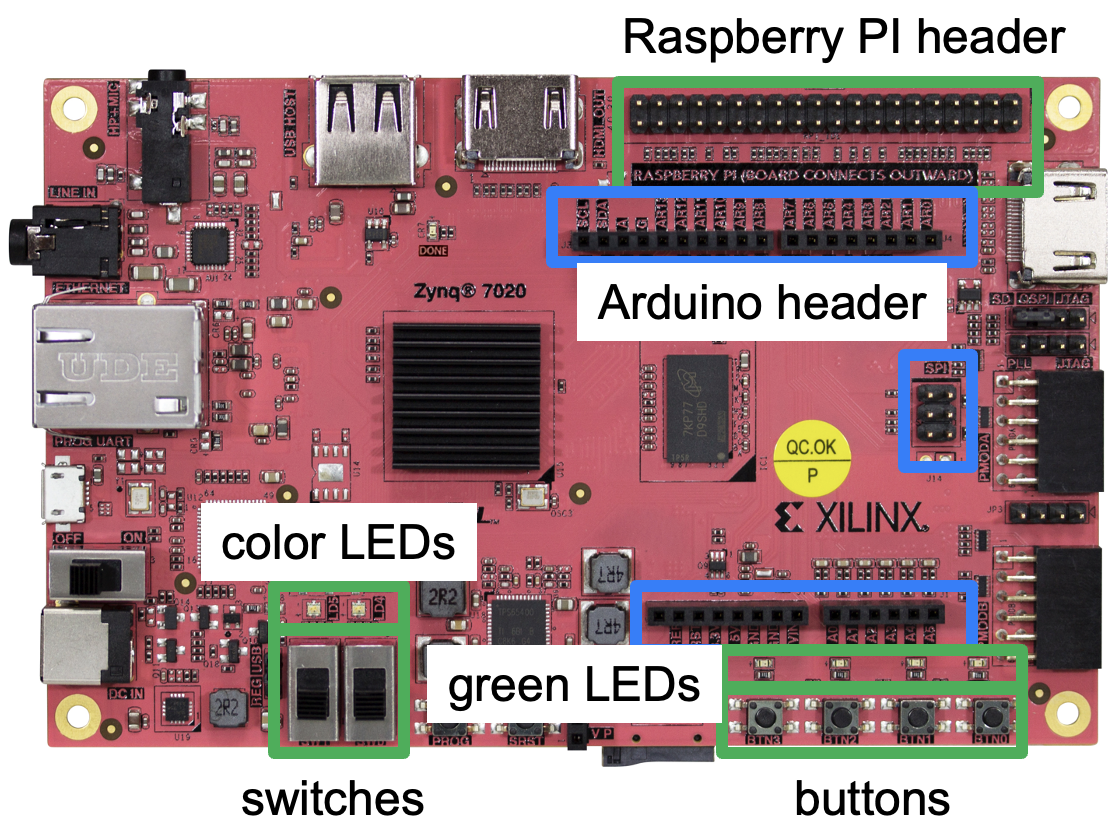
- The 4 green LEDs (LD0..LED3) and 2 color LEDs (LD4-5R/G/B) are output pins.
- The buttons (BTN0..BTN3) and switches (SW0..SW1) are input pins.
- The Arduino header contains 14 digital I/O pins (AR0..AR13) that can be individually set to input or output, as well as 6 analog input pins (A0..A5). Two I/O pins (AR_SCL and AR_SDA) are pins for the I2C (Inter-Integrated Circuit) protocol.
- The Raspberry PI header contains 26 I/O pins that can be individually set to input or output. (Some of the pins are hardwired to ground or are not connected, and cannot be routed to/from the switchbox.)
Raspberry PI headers
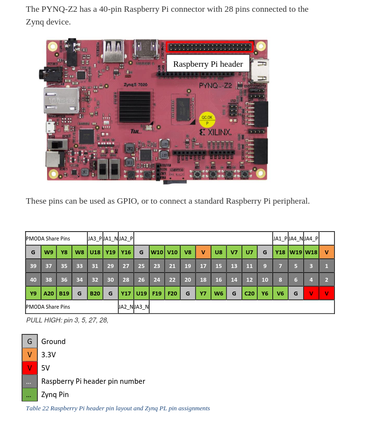
See Section 18 in the pynq user documentation for more information.
Arduino headers
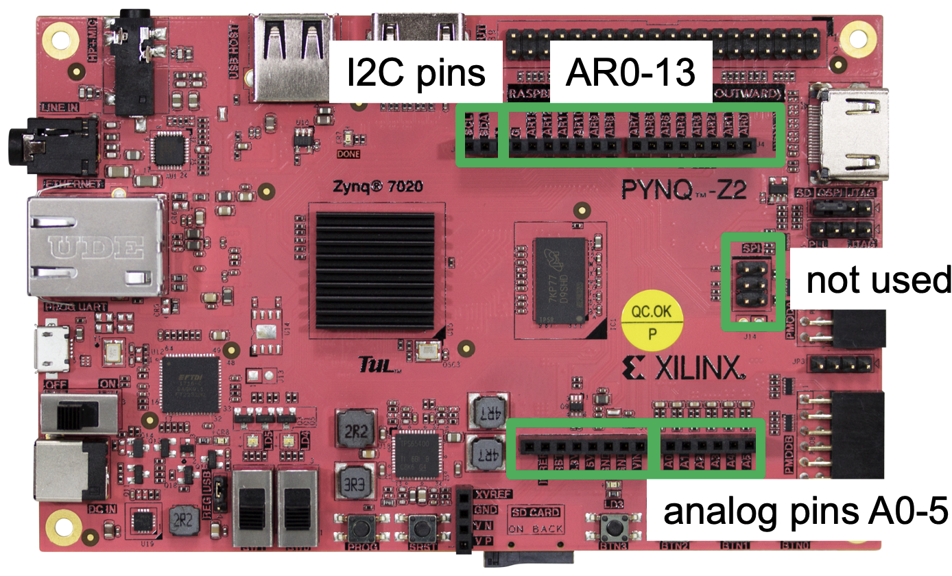
See Section 17 in the pynq user documentation for more information.