MQTT Communication

MQTT is a communication protocol that can be used to communicate (wirelessly) between the robots and a laptop.
MQTT builds on top of IP based communication, in this case using the WiFi connection to the iotroam WLAN provided by the connectivity board.
Please refer to the illustration below to understand the overall topology of the system setup:
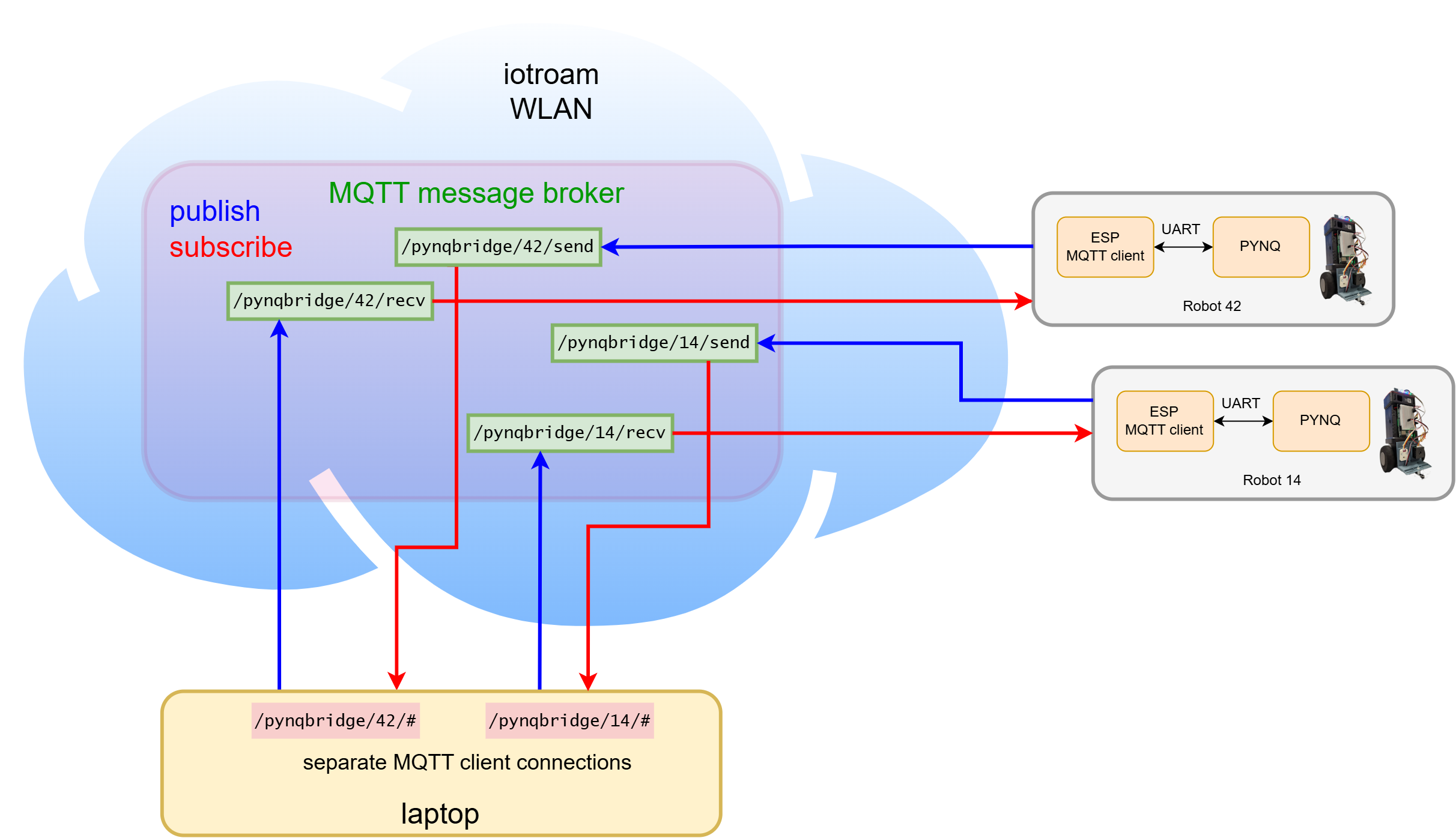
ℹ️ Information Each robot has a separate account on the MQTT message broker and each team will receive the accounts for the computer connections to the robots they use.
Connectivity board
The connection through WiFi over the iotroam WLAN to the MQTT message broker is provided by the ESP32C3 board shown below:

It has status LEDs that show whether a WiFi connection has been established and if messages are being transmitted or received.
- If the WiFi led (middle) flashes slowly it is connecting to the WiFi.
- If the user led (right) is on and the WiFi led flashes quickly it is connecting to MQTT.
- If both the user led and the WiFi LED are solid on, the board is connected to the WiFi and the MQTT server.
- The Tx/Rx LED (left) flashes when a messages is being received/transmitted.
The setup is designed to handle complex data processing and communication tasks. The MQTT protocol serves as the foundation of the robots' communication network, ensuring continuous and secure data exchange between the ESP processor on the connectivity board and the MQTT server. In addition, another type of communication is necessary between the main PYNQ board and the ESP32C3. For this communication, the UART protocol is used in the inter-board network.
The UART communication between the PYNQ, the ESP32C3 and back is structured as follows.
- A message starts with a 32bit unsigned integer number that contains the size (in bytes) of the message payload
- The message payload with the length specified.
           ┌───────────┬─────────────────────┐
size:      │32bit     │ (msg size)*8 bit  │
content:   │msg size  │ Message           │
           └───────────┴─────────────────────┘
The ESP32C3 is connected via to the UART via pins AR0 and AR1 of the PYNQ board. To connect these to UART0 use:
Pins AR2, AR3 are also connected to the ESP32C3, they indicate if it is ready to accept data (AR3) or if it is transmitting data (AR2).
UART (Universal Asynchronous Receiver-Transmitter) protocol
The ESP boards have already been flashed with the necessary firmware for handling UART input and communicating with the server. It is configured to communicate at 9600 baud (bits/second). Since the UART protocol adds an overhead of 1 start bit and 1 stop bit to every 8 bits of data payload, it can effectively communicate 960 bytes of data per second.
As described in the UART library documentation in the libpynq documentation you can send and receive bytes with high-level UART functions.
Accessing MQTT from the Laptop
You will use python to access the MQTT message broker to communicate with the robots.
Example python scripts will be provided to set up the communication.
ℹ️ Information Every robot communicates on topics that include the specific robot number and the laptop requires credentials to connect to it.
⚠️ Warning Unique client IDs should be used to connect a laptop to the MQTT broker. Any existing clients with the same name will loose their connections, potentially leading to unexpected, silent failures.