Macros | |
| #define | NUM_SWITCHBOX_NAMES 40 |
Typedefs | |
| typedef enum io_configuration | io_configuration_t |
Enumerations | |
| enum | io_configuration { SWB_GPIO = 0x00, SWB_Interrupt_In = 0x01, SWB_UART0_TX = 0x02, SWB_UART0_RX = 0x03, SWB_SPI0_CLK = 0x04, SWB_SPI0_MISO = 0x05, SWB_SPI0_MOSI = 0x06, SWB_SPI0_SS = 0x07, SWB_SPI1_CLK = 0x08, SWB_SPI1_MISO = 0x09, SWB_SPI1_MOSI = 0x0A, SWB_SPI1_SS = 0x0B, SWB_IIC0_SDA = 0x0C, SWB_IIC0_SCL = 0x0D, SWB_IIC1_SDA = 0x0E, SWB_IIC1_SCL = 0x0F, SWB_PWM0 = 0x10, SWB_PWM1 = 0x11, SWB_PWM2 = 0x12, SWB_PWM3 = 0x13, SWB_PWM4 = 0x14, SWB_PWM5 = 0x15, SWB_TIMER_G0 = 0x18, SWB_TIMER_G1 = 0x19, SWB_TIMER_G2 = 0x1A, SWB_TIMER_G3 = 0x1B, SWB_TIMER_G4 = 0x1C, SWB_TIMER_G5 = 0x1D, SWB_TIMER_G6 = 0x1E, SWB_TIMER_G7 = 0x1F, SWB_UART1_TX = 0x22, SWB_UART1_RX = 0x23, SWB_TIMER_IC0 = 0x38, SWB_TIMER_IC1 = 0x39, SWB_TIMER_IC2 = 0x3A, SWB_TIMER_IC3 = 0x3B, SWB_TIMER_IC4 = 0x3C, SWB_TIMER_IC5 = 0x3D, SWB_TIMER_IC6 = 0x3E, SWB_TIMER_IC7 = 0x3F, NUM_IO_CONFIGURATIONS } |
Functions | |
| void | switchbox_init (void) |
| void | switchbox_set_pin (const io_t pin_number, const io_configuration_t pin_type) |
| void | switchbox_reset (void) |
| void | switchbox_destroy (void) |
| io_configuration_t | switchbox_get_pin (const io_t pin_number) |
Variables | |
| char *const | switchbox_names [NUM_SWITCHBOX_NAMES] |
Detailed Description
The switchbox enables run-time (re)mapping of I/O pins.
For example, the transmit output of UART 0 (SWB_UART0_TX) can be mapped to analog pins IO_AR0 & IO_AR1. Or the output of PWM 0 (SWB_PWM0) can be mapped to green LED 0 (pin IO_LD0). Or the output of PWM 0 (pin SWB_PWM0) can be mapped to the green component of color LED 0 (pin IOB_LD0).
- Warning
- Switchbox functions (dis)connect IO pins (outside world) to FPGA hardware (on the Zynq 7020). IO pins are named IO_* (e.g. IO_LD0) and are of type io_t defined in pinmap.h. The FPGA hardware is named SWB_* (e.g. SWB_UART0) of type (io_configuration_t) defined in switchbox.h.
Macro Definition Documentation
◆ NUM_SWITCHBOX_NAMES
| #define NUM_SWITCHBOX_NAMES 40 |
Definition at line 135 of file switchbox.h.
Typedef Documentation
◆ io_configuration_t
| typedef enum io_configuration io_configuration_t |
Enumeration Type Documentation
◆ io_configuration
| enum io_configuration |
Definition at line 62 of file switchbox.h.
Function Documentation
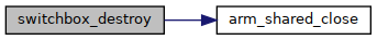
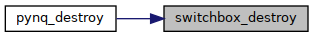
◆ switchbox_destroy()
| void switchbox_destroy | ( | void | ) |
Resets all pins of the switch box to be input.
Definition at line 6 of file switchbox.c.
◆ switchbox_get_pin()
| io_configuration_t switchbox_get_pin | ( | const io_t | pin_number | ) |
Sets the mode of a specified pin.
- Parameters
-
pin_number The IO pin number.
- Returns
- The FPGA hardware the IO pin is connected to.
Definition at line 162 of file switchbox.c.
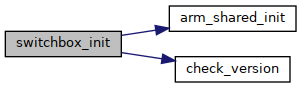
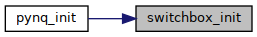
◆ switchbox_init()
| void switchbox_init | ( | void | ) |
Initializes the switch box.
Initializes the shared memory and sets the io switch base address
Definition at line 3 of file switchbox.c.
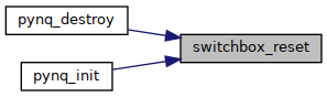
◆ switchbox_reset()
| void switchbox_reset | ( | void | ) |
Resets all pins of the switch box to be input.
Definition at line 5 of file switchbox.c.
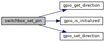
◆ switchbox_set_pin()
| void switchbox_set_pin | ( | const io_t | pin_number, |
| const io_configuration_t | pin_type | ||
| ) |
Set the type of a switch pin.
- Parameters
-
pin_number The number of the IO pin to connect (IO_*, IO_LD0). pin_type The FPGA hardware to connect to (SWB_*, e.g. SWB_PWM0).
Definition at line 126 of file switchbox.c.
Variable Documentation
◆ switchbox_names
| char* const switchbox_names[NUM_SWITCHBOX_NAMES] |
Taken from scpi_names.h, lookup table for channels in the mapping_info function.
Definition at line 2 of file switchbox.c.